

RALLIVEX PrecisionQuoteSend Enquiry / Request a Quote

Define the faces, pockets and features that matter.

CNC milling is a route to consider for components with planar faces, pockets, profiles, holes and features accessed from different directions. The drawing should make the functional relationships between those features clear.

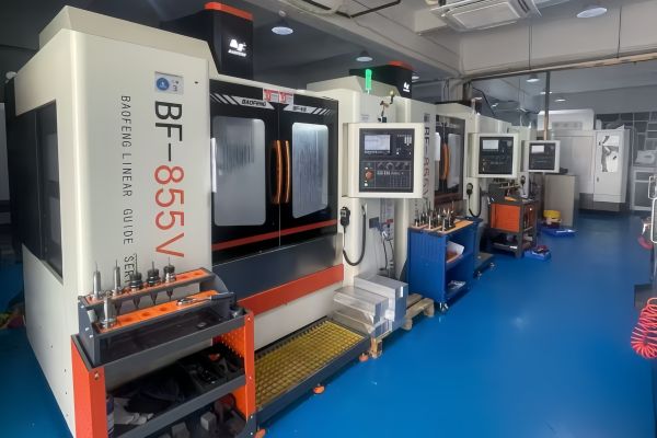
CNC milling equipment photographed for the former Rally Machining website
Workshop photograph · former Rally Machining website
Illustrative CNC milling scene
Illustrative process scene

Pockets and internal corners

Tool access affects how a pocket can be machined. Describe pocket depth, internal radii, narrow sections and any surfaces that must remain sharp. Do not replace the drawing with a universal minimum corner radius: the feasible approach depends on tooling, reach, material and the surrounding geometry.

Thin sections and workholding

A thin wall or slender feature can make supporting the part more difficult. Explain which surfaces may be clamped and which must remain cosmetic or functional. The review should consider the machining sequence and access to remaining features as material is removed.

Holes, threads and references

Specify thread type, size, depth and any special acceptance requirements. Identify the datum features used to locate hole patterns or mating surfaces. A consistent reference scheme helps the manufacturing and inspection teams interpret the same requirements.

Surface condition and finishing

Separate as-machined functional surfaces from cosmetic faces and areas requiring a subsequent finish. Identify masked regions and whether drawing dimensions apply before or after treatment. Provide an approved appearance sample where written colour descriptions are not sufficient.

Project questions

Should every feature have the tightest possible tolerance?

Assign tolerances from the function and assembly requirements. Unnecessary tight requirements can add process and inspection work; critical features should remain clearly identified.

Can extra machining axes solve every access problem?

No. Tool reach, collision clearance, workholding and part geometry still need review. More axes do not remove all manufacturing constraints.

Details to include in your RFQ

Project preparation checklist — not a capability specification
TopicInformation to prepare
GeometryPockets, internal corners, faces and accessible features
DrawingDatums and critical dimensions
FinishFunctional versus cosmetic surfaces

On narrow screens, scroll the table horizontally.

Project planning

Questions that change a milling plan

The same outside dimensions can require very different setups depending on pocket access and the surfaces that must relate to one another.

01

Access and reach

Call out deep cavities, narrow slots, undercuts and internal radii. A model shows their shape, but the drawing should identify features whose geometry cannot be changed to suit a tool.

02

Holding sequence

Identify cosmetic faces and surfaces that may be used for fixturing. Thin walls and interrupted features can change how the workpiece is supported between roughing and finishing.

03

Verification

Specify which hole patterns, faces or bores must be measured relative to a common datum. Ask how the agreed measurement will be recorded when the feature is difficult to reach after assembly or finishing.

Project enquiry

Discuss your manufacturing project

Describe your requirements. Attach a drawing if available.

Send a project enquiry or request a quote

Describe your project or quality question below. Drawings are optional; if you have them, accepted formats are STEP, STP, IGES, DXF, DWG, PDF and ZIP. Your request is received only after a confirmation reference appears. For questions, email sales@rallivex.com or contact us on WhatsApp: +86 137 3607 8178.

You can submit without a drawing. If attaching files: STEP, STP, IGES, DXF, DWG, PDF or ZIP; up to 10 files, 20 MB each and 25 MB total. Files are sent only when you submit.