
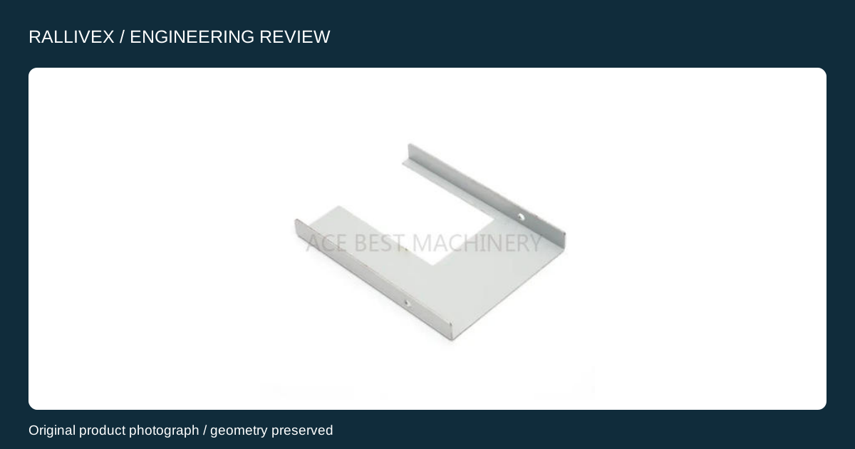
1. Review the formed part first
A hole near a sheet-metal bend should be reviewed in the finished assembly, not only in the flat pattern. Identify the fastener, locating pin or connector that must pass through it and the surface that determines its position. The useful question is whether the formed feature meets that function after the bend is made.
Provide material grade, thickness, inside bend radius and the intended formed dimensions. Keep the flat pattern identified as a manufacturing aid unless the drawing explicitly makes it controlling. An attractive flat layout does not settle the relationship between holes on different flanges.
2. Define the hole-to-bend reference
The Protolabs Network sheet-metal guide discusses holes, bend features and design limits. Uptive’s forming-near-holes guidance relates clearance to thickness and bend radius. These are reasons to review the actual geometry with the forming route; supplier guidance is not a universal minimum that can be transferred unchanged to every part.
State whether a quoted distance is measured from the hole edge, hole center or bend tangent. Show that reference clearly on the drawing. The ACE sheet-metal photos provide examples of flanges and cut features, but photographs cannot establish their thickness, tooling or dimensional acceptance.
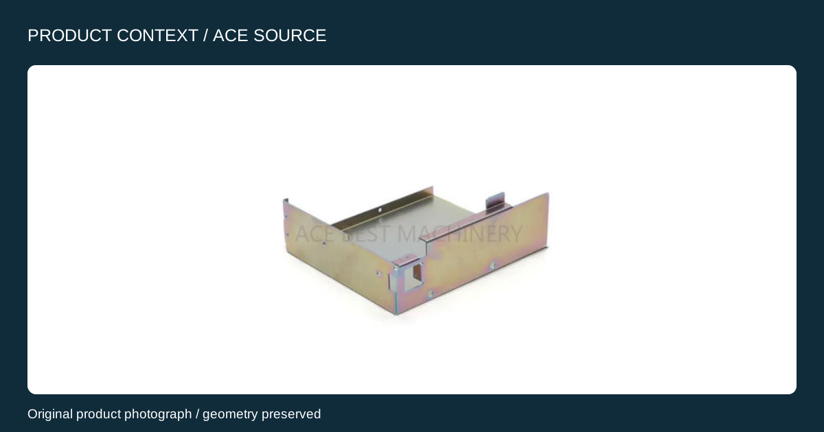
3. Compare alternatives by function
If the proposed spacing is unsuitable, review whether the hole can move, the flange can change, a relief can be added or the operation sequence can be reconsidered. Treat each option as a proposed engineering change. Do not enlarge a locating hole into a slot merely because the slot is easier to manufacture.
For a hypothetical mounting bracket, a clearance slot may be acceptable on one fastener while a second hole controls location. Mark that distinction and identify the required adjustment direction. Ask the manufacturer to return the proposed change on a marked model so purchasing and engineering review the same geometry.
4. Inspect in the agreed formed condition
Agree which surface supports the part during inspection and which dimensions apply after bending. If a feature is measured before assembly but used after assembly, document any support or restraint required by the design. Avoid accepting a flat-pattern measurement as evidence for a formed relationship that it does not measure.
For the first sample, request results tied to the relevant drawing characteristics and part revision. Record any approved design exception. The review map separates reference definition, forming review and final acceptance so that a manufacturing adjustment does not silently redefine the interface.

5. Prepare the enquiry package
Send RALLIVEX the formed drawing, material, thickness, finish and quantity. Highlight holes close to bends and explain their assembly role. A written enquiry can start the discussion when CAD is unavailable. State which dimensions are fixed and which can be reviewed for a manufacturing alternative.
Ask the proposal to distinguish the submitted design from any modified option and to identify inspection assumptions. Use the stamping service and quality pages below to continue the project review. These photographs illustrate product forms, not a guaranteed tolerance or a record of a particular customer’s approval.