
1. Identify which part of the pocket must be deep
A deep-pocket milling review should begin with the function of the cavity, not a single maximum-depth question. Identify what occupies the pocket, which surfaces locate or seal the assembly, and which regions only provide clearance. That distinction lets the engineer consider useful alternatives without changing a functional interface by accident.
For a hypothetical electronics housing, the board seat may need a controlled position while unused space above it has more freedom. Mark those regions on a section view and state which dimensions are fixed. Include the material, finish and quantity. A supplier can then distinguish the required finished geometry from details you are willing to reconsider.
2. Check reach as an assembly, not a cutter length
Protolabs warns that deep, narrow pockets and features beside tall walls can create cutter-deflection problems. Sandvik Coromant recommends minimizing tool overhang and choosing a practical diameter-to-length relationship in end milling. These are planning principles; neither establishes a universal pocket depth that every machine, material and tool assembly can achieve.
Ask the manufacturing review to consider the cutter, neck or shank, holder and surrounding part together. Reaching the floor is insufficient if another part of the assembly interferes with a wall on the required path. Supply the complete local geometry, including nearby ribs and ledges, rather than a cropped image showing only the bottom surface.
3. Separate corner clearance from positioning surfaces
Protolabs illustrates internal-corner reliefs as an option when a rectangular item must fit inside a milled enclosure. A larger corner radius or local relief can be worth reviewing, but only if the assembly allows it. Do not increase a radius across a locating or sealing feature merely to make the tool choice simpler.
Use a marked drawing to distinguish the vertical inside-corner radius from the floor-to-wall transition. State the mating-part envelope and the required clearance. If a supplier suggests a relief, request its extent and location on a revised model before approval. The section below addresses another independent check: clearance around the tool assembly as it approaches the pocket floor.

4. Include chip removal in the process review
Sandvik treats chip evacuation, tool deflection and vibration as relevant limits in slot and pocket operations. Its guidance also distinguishes different entry and roughing approaches. A quoted route should therefore account for how material leaves the cavity; an apparently accessible cutting edge does not by itself establish a stable operation.
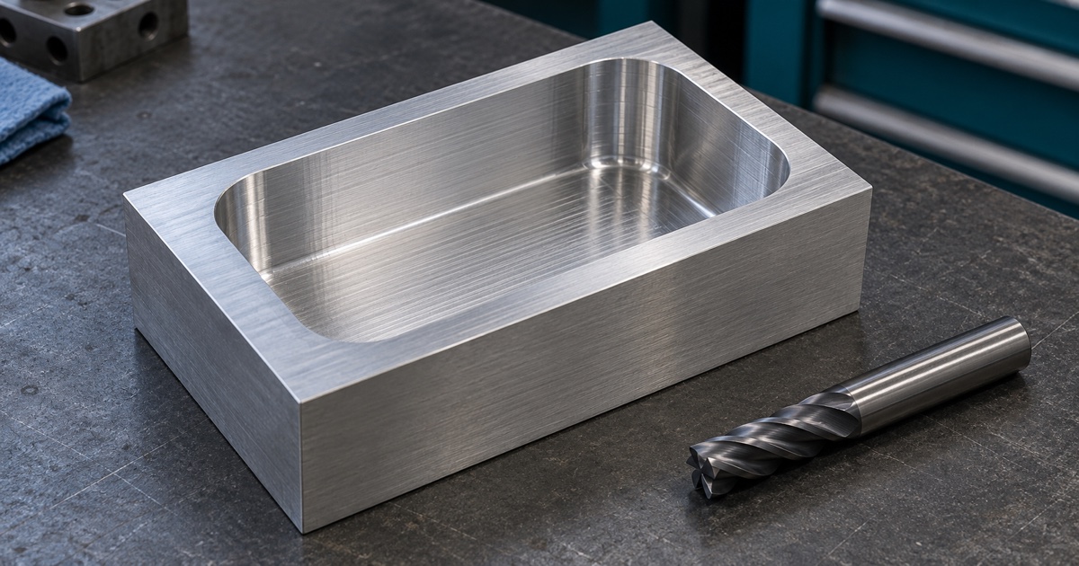
Ask which regions require separate roughing and finishing attention and whether any design change is proposed. Leave cutting data and equipment selection to the qualified manufacturing review. For the purchasing decision, compare the unchanged functional requirements, the proposed geometric deviations and the evidence needed for acceptance. Do not infer production cycle time or guaranteed finish from a generic tool photograph.
5. Send an access-focused enquiry
For RALLIVEX, describe the cavity function, identify the deepest required region and provide the current drawing revision when available. Include material, quantity, finish, critical dimensions and acceptable design freedoms. A written project description is enough to begin an enquiry; a model and section views help resolve access questions as the review develops.
Request a clear distinction between the design as submitted and any proposed alternative. For each alternative, ask which interface remains unchanged and what must be approved before machining. Review inspection of difficult features as a separate requirement using the linked inspection-planning guide. Tool access and measurement access are related questions, but proving one does not prove the other.