
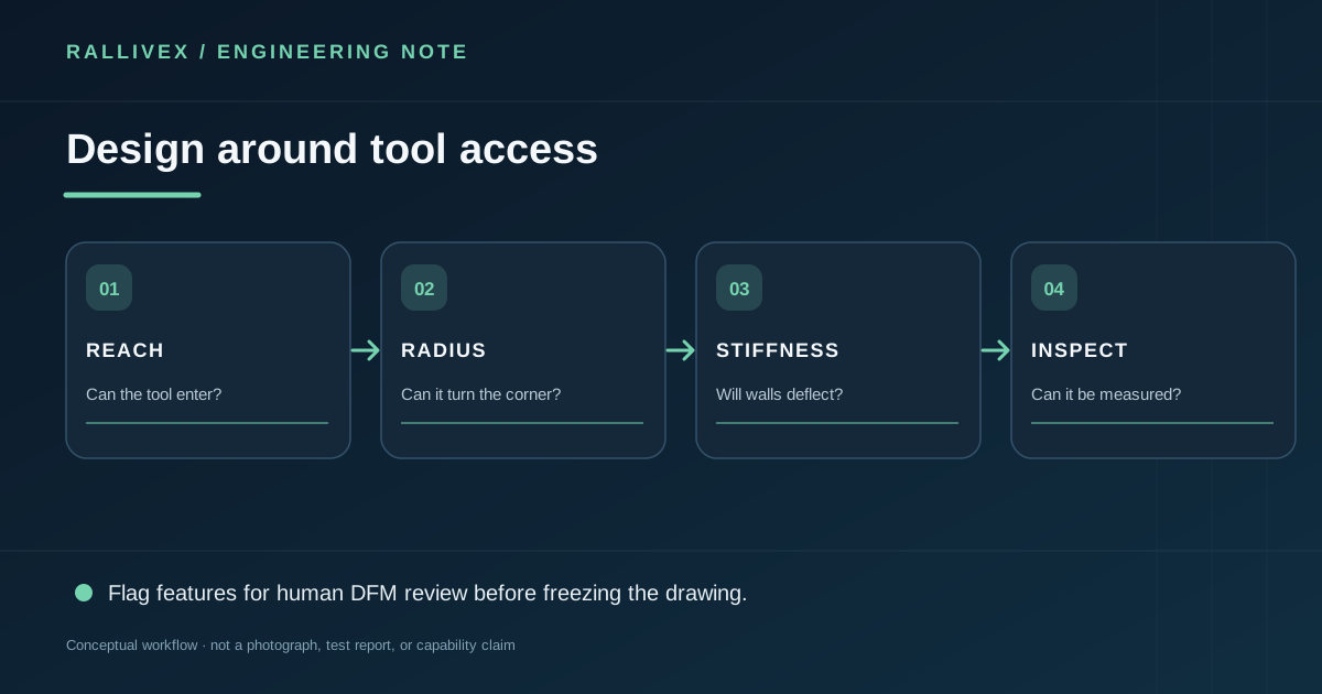
CNC milling removes material with a rotating tool. The tool has a real diameter, needs a path into the part and must clear fixtures and neighboring walls. Designs that ignore access can still be possible, but may require smaller tools, extra setups or a process change.
Give internal corners a realistic radius
An end mill cannot create a perfectly sharp inside corner in a conventional pocket. If a mating part needs a square edge, consider a corner relief, a mating-part chamfer, or another manufacturing method. Avoid choosing an arbitrary radius solely from a generic rule; the selected tool and pocket depth matter. Ask for a DFM review where the corner controls assembly.
Review depth and wall stiffness together
Deep narrow pockets can force long tool reach and make chip evacuation difficult. Thin walls may deflect under cutting load or during clamping. One feature may be feasible by itself yet troublesome next to another feature. Specify the functional minimum wall and pocket geometry, then let the machinist evaluate tool access and sequencing. If a slot does not require a flat bottom, say so; if it does, make that explicit.
Control only the geometry that matters
Put tight tolerances and surface-finish requirements on functional features, not every face. Define a sensible datum scheme, especially for holes that mate with another component. Explain whether dimensions apply before or after coating. Plan how burrs and edges will be treated where a part is handled, sealed or assembled.
Emerging practice: use automated DFM as a conversation starter
Software can flag inaccessible corners, long-reach tools or thin walls early, but an automated warning is not a final manufacturability verdict. The result depends on chosen stock, fixturing, cutter library and acceptable process changes. The strongest workflow is a human review of the flagged features against the part's function: identify which features are fixed, which can change and what inspection will prove the revised design. NIST's work on model-based manufacturing emphasizes the need for design, process and quality data to communicate in both directions; the useful outcome is a documented design decision, not merely a green “pass” badge.
Before RFQ, view the model as a tool path: can a cutter reach every feature, can the part be held, and can the critical dimension be measured? These questions guide a productive DFM conversation. Next step: send the STEP model and annotated drawing via request a quote, highlighting the features you cannot change.