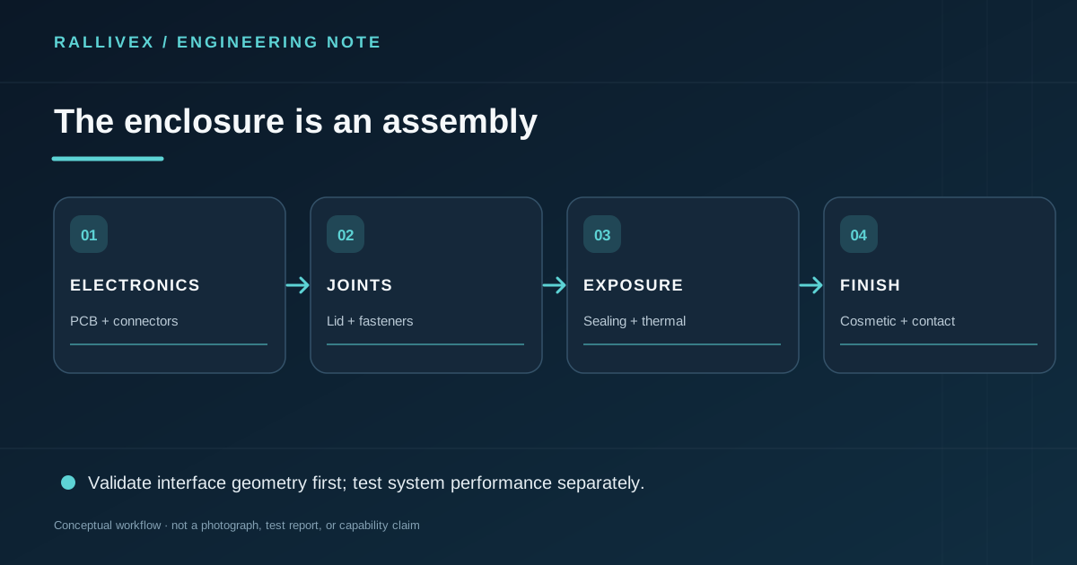
An enclosure is not merely a hollow aluminum block. It must locate electronics, admit connectors, protect users and often transfer heat or withstand an environment. If these functions are defined late, a simple machining quote can hide expensive assembly changes.
Map the interfaces first
Create a basic interface list: PCB mounting points, connector cutouts, lid and gasket locations, fasteners, cable bend space and any external mounting datum. Check the stack-up from the components that actually mate. Leave tool and fastener access where the assembly sequence needs it. Identify cosmetic faces separately from internal machined faces so the finish requirements do not spread unnecessarily.
Treat sealing as a system requirement
A nominally tight enclosure is not automatically water- or dust-resistant. Seal performance depends on joint geometry, gasket selection, fastener loading, ports, assembly and testing. If an IP rating is required, state the exact target and who will validate the assembled product. Do not assume a machined enclosure alone carries the rating. For thermal performance, provide the device heat load and ambient condition; a material name or exterior fin pattern does not prove the result.
Review machining and finishing together
Internal corner radii, pocket depth and thin ribs affect tool access. Anodizing or another finish may affect visible color and critical fits, so specify which surfaces are cosmetic, which require electrical contact and which should be masked. Define a drawing revision that includes the final components; otherwise, suppliers may quote different interpretations of the same enclosure.
Emerging practice: validate the enclosure as a digital assembly
Modern CAD makes it easy to check component clearances and access before cutting metal, but the model should include more than the enclosure shell. Bring in connector envelopes, cable bend zones, gasket compression interfaces, fastener heads and the expected service path. Record which checks are geometric simulations and which still need a physical prototype or product-level test. A digital twin is meaningful only when its assumptions and measured feedback are defined; a rendered enclosure image alone does not establish sealing or thermal performance.
Share the enclosure model, assembly view and critical interface drawing for an RFQ review. If the design is still changing, request prototype feedback first and state which features are provisional. The CNC milling page explains the manufacturing route at a service level; this article owns the enclosure design question.