
A “tight tolerance” is not one number that applies to an entire part. The achievable and economical range depends on feature size, geometry, material, setup, finishing and measurement. A quote that promises a universal tolerance without reviewing the drawing cannot tell you how the mating assembly will perform.
Translate function into controls
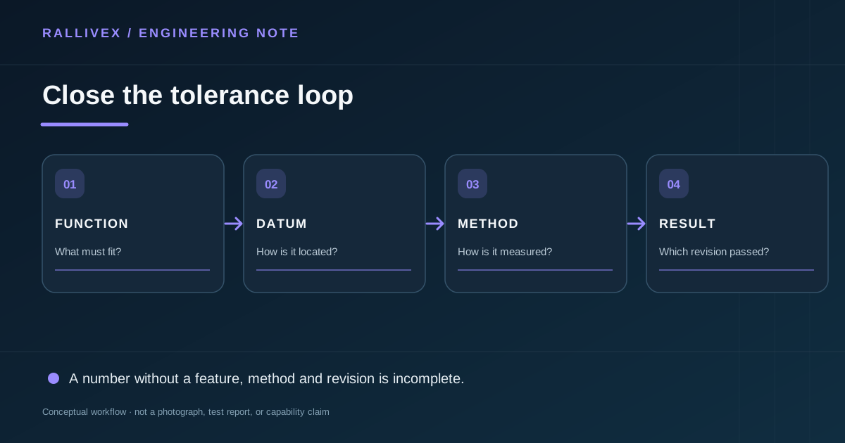
Identify the surfaces that locate the part in the assembly. Then define the dimensions and geometric relationships that protect clearance, sealing, alignment or motion. ASME Y14.5 provides a common drawing language for datums and geometric tolerancing; use the version and conventions agreed with the supplier. A 3D model conveys shape, while a controlled drawing or model-based definition must convey acceptance requirements.
For example, a hole pattern may need position relative to two mounting faces more than individually tight hole-to-edge dimensions. A sealing land may need flatness and surface condition rather than a blanket high-precision callout on unrelated faces. These are design examples, not substitute specifications for a particular part.
Match each critical requirement to a measurement method
Ask how the supplier will locate the part for inspection, what instrument will be used and whether the method can resolve the tolerance in question. NIST treats traceability as a documented measurement chain, not as a marketing label. If your purchasing rules require calibration evidence, request it in the RFQ. Agree on sample size, reporting format and who resolves ambiguous or out-of-tolerance results.
Emerging practice: return measurement data to engineering
Digitized inspection can link a measured result to the specific drawing characteristic and revision instead of leaving a PDF report detached from design intent. NIST has researched the connection between STEP-based product definitions and QIF-based quality information. For a buyer, the practical question is whether the supplier can identify which feature was measured, by what method and against which revision. AI-assisted anomaly detection may highlight patterns in those records, but it cannot replace a defined datum, a capable measurement system or an agreed acceptance rule.
Finishing complicates acceptance: an anodized or plated dimension may differ from the machined dimension. State which state is controlled and protect masking or contact areas as needed. Next step: identify your three to five most critical features and send the drawing for a project-specific review. Ask for inspection scope in the written quotation.