
Start with the enclosure interfaces
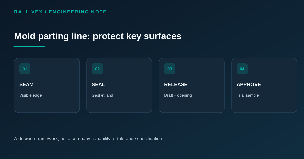
An enclosure has surfaces that do different jobs: a lid may seal against a gasket, a bezel may be visible to the user, and an internal wall may locate a board. Mark these regions on the model before a toolmaker proposes the parting line. A seam crossing an uninterrupted cosmetic face is one issue; mismatch or flash at a sealing land can be a functional issue. The same line placement should be reviewed against both the assembly and the intended molding route.
Protolabs explains that the meeting line between mold halves affects mold opening, draft, appearance and possible secondary work. The legacy Rally plastic-electrical-enclosure page describes both machined and molded product routes, but does not establish a fixed RALLIVEX tool design or molding capability. This guide addresses the design decision, not a promise of a particular mold construction.
Sketch the opening direction and draft
For each candidate parting line, indicate the direction in which the two mold halves separate. Check ribs, clips, connector cutouts and exterior texture against that opening direction. A detail that appears harmless in the assembly may create an undercut or require a side action when viewed from the tool. Autodesk defines the parting plane as the contact interface of the stationary and moving mold halves; its location is therefore tied to how the part is released.
If an enclosure can be split at an existing corner, that may make the seam less visible, but do not turn the idea into a universal rule. Corners, radii and local shutoffs must be reviewed with the actual resin and geometry. Record any proposed design change separately so the accepted CAD revision remains clear.
Protect sealing and appearance zones
Add a drawing view that marks no-seam or controlled-seam regions, the gasket contact path, visible exterior faces and acceptable post-trim areas. Define what the assembly can tolerate rather than saying simply “no flash.” If a cable entry or screw boss interrupts the edge, ask how the parting surface will pass it and where any vestige will remain. A decorative texture should also be discussed before tool design because draft and seam visibility interact.
Protolabs notes that mold-edge mismatch and flash can affect appearance and fit. A trial part may reveal a local issue that the CAD image did not predict. Plan a documented appearance and fit review using the specified lighting, mating parts and gasket condition where those details matter.
Approve the tool concept and trial sample
Request a parting-line drawing alongside proposed gate, ejection and side-action locations. Check that the tool concept respects the protected zones and that the selected material and shrinkage assumptions are stated. The design team should approve a revision-controlled concept before steel is cut, then compare trial parts to the agreed seam and sealing criteria.
For an RFQ, provide the enclosure model, assembly drawing, resin specification, target quantities, cosmetic views, sealing surfaces and acceptance method. Ask the supplier to state any seam, draft or undercut exceptions. A parting line is a negotiated design feature with inspection consequences, not a hidden manufacturing detail to discover after tooling.