1. Separate the finished surface from the casting stock
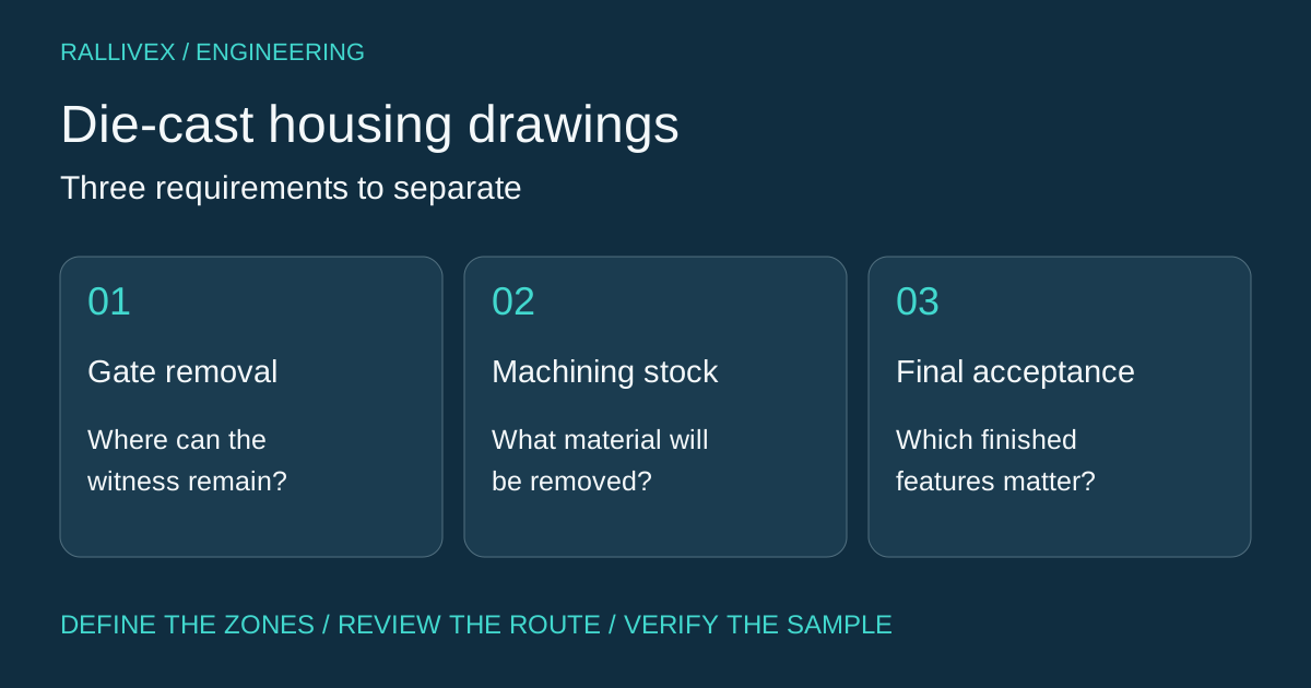
A die-cast housing drawing should distinguish three things: the required finished geometry, the material intentionally left for machining, and the permitted condition where a gate is removed. A gate witness is not automatically machining allowance. Mark each affected surface and agree the manufacturing state to which its dimensions and appearance requirements apply before approving the tool concept.
This guide addresses a metal housing that will be cast and then selectively machined. It does not prescribe a universal stock thickness or gate location. The casting process, alloy and part geometry must be identified first. A machined-from-billet prototype can help assess assembly fit, but its smooth exterior does not establish an achievable as-cast surface specification.
2. Give gate removal its own acceptance zone
The International Zinc Association explains that available gate area and gate thickness influence trimming and the witness left behind. Its zinc die-casting guidance also notes that a parting-line witness may remain after trimming. These are reasons to review the proposed gate and parting layout together; zinc-specific dimensional rules should not be transferred directly to an aluminum housing.
For each proposed removal zone, state whether a residual projection is permitted, whether local undercut below the surrounding surface is acceptable, and which adjacent faces must be protected. Tie any limits to a defined reference surface. A general instruction to remove the gate leaves these questions open. Request a marked-up trimming proposal and sample acceptance criteria instead of relying on a photograph of a different part.
3. Specify machining stock with the finished face
MRT Castings describes machining allowance as additional cast material intended for later removal. Its guidance explains that allowance depends on casting size, process and geometry, and warns that excessive removal adds machining and can expose casting defects. Ask the casting and machining reviewers to agree the stock envelope for each face, including the relevant casting variation and draft. More stock is not automatically a safer design.
In a hypothetical housing with a machined gasket land, distinguish the final sealing plane from the raw flange surface. The stock must support the agreed cleanup operation while retaining the required finished wall and flange geometry. Identify what remains as cast. If the proposed gate is near that flange, separately review its removal zone; do not assume that machining the sealing face also removes a witness on the outside wall.

4. Make the reference transfer inspectable
The casting and final-machining documents should describe compatible part states. Ask the supplier to identify the surfaces used to locate the raw housing for its first machining operation, then the finished references used for subsequent features and inspection. This is a review question about the proposed route, not a claim that one fixture arrangement works for every housing.
For example, a mounting-hole pattern may be accepted relative to a finished face while an external cosmetic wall remains as cast. State which relationship matters to assembly, and distinguish it from the temporary locating contacts used during machining. Keep the casting model, finished model and drawing revisions connected so a tooling change does not silently invalidate the machining or inspection plan.
5. Agree evidence before approving production
Request sample evidence against the actual finished-part specification: gate-removal condition in the agreed zone, dimensions and surface requirements of machined faces, and any required relationship to as-cast features. If a housing must seal, specify the applicable functional test conditions and acceptance criteria separately. A clean-looking machined face alone is not evidence that the assembly meets a sealing requirement.
For an initial RALLIVEX enquiry, describe the housing function, alloy or open material choice, quantity, critical faces and planned finish. Attach controlled drawings and models when available; an early enquiry can begin without them. Ask for the proposed gate-removal scope, machining boundaries, reference plan and sample-verification scope to be stated in the quotation. Use the mold-tooling and CNC-milling service links below to frame the combined review.