
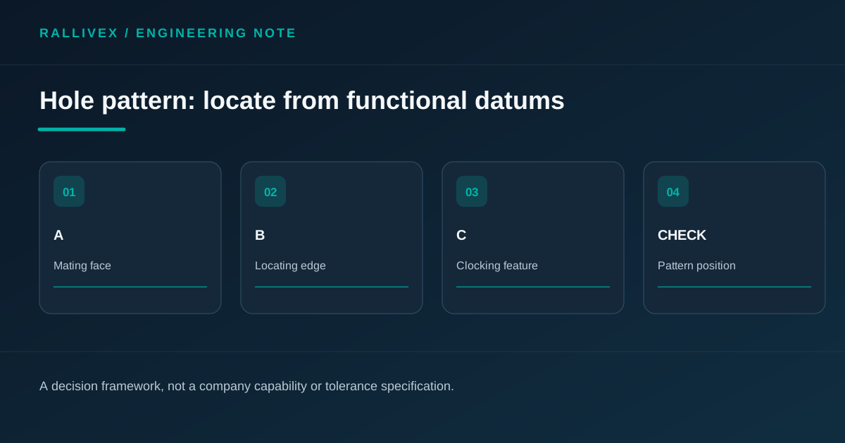
Begin with how the plate locates in assembly
A milled mounting plate may rest on a broad face, seat against an edge and rotate into position around a pin or second contact. Those functional contacts suggest a datum discussion. Mark which face establishes seating, which feature controls lateral location and which prevents rotation. If the plate instead floats on clearance screws, its datum plan may need a different rationale. Do not select datum A merely because it is the largest surface in a CAD screenshot.
ASME Y14.5 is the authoritative drawing language for datums and position tolerances when a project uses that standard. It describes datum references and degrees of freedom as part of controlling geometric relationships. The designer should specify the applicable standard edition and verify that the proposed datum features can be contacted or simulated during inspection.
Separate hole size from pattern location
A diameter callout controls hole size, while an assembly may depend on where all hole axes lie relative to the locating surfaces and to one another. Multiple independent edge dimensions can leave the intended pattern relationship unclear. A position control, when correctly applied under the chosen GD&T standard, can express that relationship with a named datum reference frame. The drawing must still include the basic geometry and any material-condition modifiers that the design actually requires.
Do not copy a sample tolerance or modifier from an unrelated bracket. Fastener clearance, mating pin fit, plate thickness and stack-up determine the acceptable zone. If only one hole truly locates and the others clear fasteners, show that functional difference. Otherwise suppliers may fixture to a convenient production edge and deliver a pattern that is easy to machine yet awkward to assemble.
Make machining and measurement interpret the same frame
The workholding plan need not physically reproduce every datum simulator, but the process must produce features that satisfy the drawing’s final reference frame. Ask how the plate will be supported across setups and which finished surfaces will be used for verification. If anodizing or another coating follows milling, state whether hole size and position requirements apply to the final or pre-finish part.
NIST’s CAD-PMI verification work treats datum features, position controls and hole dimensions as distinct product-definition information. The useful practical lesson is to transmit the controlled model and drawing together and resolve any difference before programming or inspection. A measured hole-center list with no datum setup does not by itself prove the specified positional relationship.
Write a checkable RFQ package
Send the mating assembly view, released plate model, datum scheme, hole-pattern callouts, material and finish, quantities and required inspection evidence. Identify any holes that accept pins rather than screws and any face that cannot be clamped or marked. Ask the supplier to flag inaccessible datum features and propose an inspection method before accepting the order.
An old Rally image of an aluminum base plate is useful visual context, not evidence of a specific hole-pattern tolerance. The acceptance decision belongs to the customer’s current geometry and standard. A well-defined datum reference frame lets design, manufacturing and inspection discuss the same assembly function without a blanket machine-accuracy promise.