
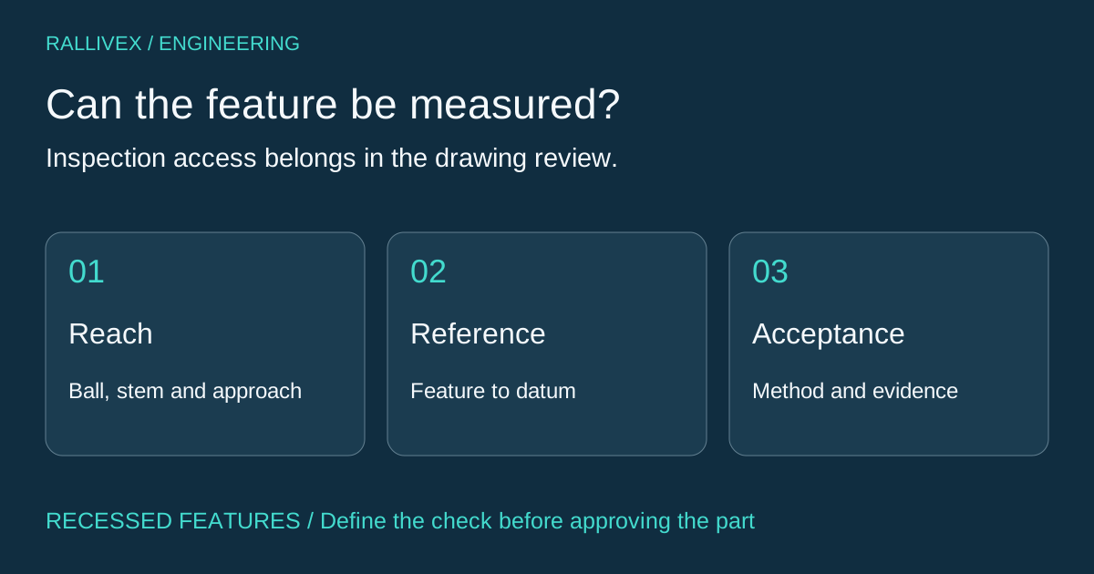
1. Define the characteristic before naming the instrument
For a hard-to-access machined feature, the inspection plan must explain what is measured, how the feature and its references are reached, and how the result supports the drawing requirement. Writing “CMM inspection” does not resolve those questions. Start with the characteristic: a bore diameter, a pocket floor position, an internal edge condition and a passage continuity check are different tasks.
Mark the relevant surfaces on a controlled drawing or section view. State whether acceptance applies before or after coating, assembly or another operation that changes access. A tool may reach a feature during manufacturing while a measuring probe cannot reach it in the finished configuration. Resolve that mismatch during the quotation review rather than after the first batch is complete.
2. Check the entire probing path
Renishaw recommends short, stiff styli and the largest suitable ball for the application. Its applications guide distinguishes overall length from effective working length: the stem can foul a feature before the ball reaches the intended contact. The review therefore needs the entrance clearance, the target surface and the approach direction, not just a nominal probe length.
For a hypothetical recessed bore, ask whether the ball can enter, whether the stem clears the entrance during contact, and whether the required reference surfaces can be established in the same measurement plan. A longer extension is not automatically a satisfactory answer. Request confirmation that the proposed configuration is suitable for the actual depth, geometry and inspection requirement; do not infer capability from a generic machine photograph.
3. Keep the measurement reference visible in the plan
An accessible diameter measurement does not by itself prove the location of that bore relative to the specified datums. Identify the drawing references and the sequence used to establish them. If the part must be reoriented or re-fixtured, ask how the relationship between the measured feature and those references is retained or reconstructed.
The sketch below separates two review questions: can the sensing element reach the surface without interference, and can the measurement be related to the required datum? It is not a probe-selection chart or a fixture prescription. On a thin or compliant component, also explain the support condition used for inspection so the reported result has an agreed physical meaning.

4. Evaluate alternative methods against the same requirement
When contact access is unsuitable, an alternative method must still answer the original measurement question. A NIST study describes computed tomography as a nondestructive route to internal three-dimensional measurements while emphasizing the need to assess dimensional-metrology performance and reconstruction artifacts. That research does not make CT a universal acceptance method for every material, size or tolerance.
If CT is proposed, request evidence that its measurement performance is suitable for the specific part and characteristic. If a sectioned sample is proposed, agree which units may be sacrificed and what conclusions can be drawn about the remaining batch. A visual image showing that a passage exists is not the same result as a dimension tied to a datum. The methods discussed here are review options, not claims that RALLIVEX owns particular inspection equipment or includes these methods in every quotation.
5. Agree the evidence and send a focused enquiry
An inspection proposal should identify the drawing revision, characteristic, part condition, measurement method, reference setup and acceptance criteria. Request a sample report that connects results to identifiable parts and states any features the method cannot verify. Where an acceptance decision is sensitive to measurement uncertainty, resolve the decision approach with the responsible quality team before production release.
For a RALLIVEX enquiry, highlight the difficult feature, describe its assembly function, and provide the material, finish and quantity. A section view, drawing or model is useful when available, but you can start with a written description. Ask the quotation to distinguish machining scope from inspection scope and to identify any unresolved verification requirement. The quality and CNC milling pages below are the next steps for reviewing that complete part specification.