Map the surfaces by function
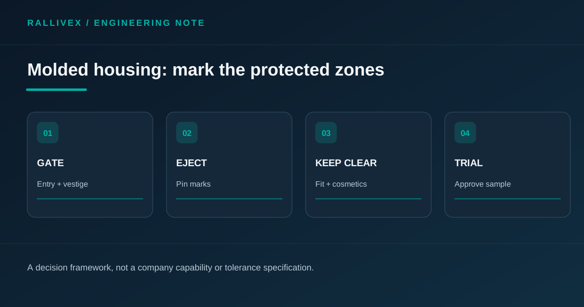
A molded housing has exterior appearance faces, gasket lands, snap features, board supports and hidden interior walls. The acceptable location for a gate vestige or ejector-pin mark depends on what each face does. A small mark on an internal non-contact wall may be harmless; the same mark on a sealing land, connector seat or visible cover can cause a fit or appearance dispute. Annotate the CAD with prohibited, preferred and review-required zones rather than writing a blanket “no marks” note.
The former Rally site presents plastic electrical enclosures as a product family, but its photographs cannot define the marking acceptance for a new customer drawing. Use the assembly and functional requirement as the authority. If the enclosure is machined rather than molded, gate and ejection marks do not apply; confirm the production route before adding these notes.
Review gate location with the fill plan
A gate is the entry point for molten polymer and its location can influence flow, weld lines, packing and visible residue. Protolabs describes gate options and the need to consider their cosmetic and processing effects. The designer should identify a face where any gate vestige can be tolerated, while the toolmaker evaluates whether that choice can fill the actual geometry with the selected resin.
Do not dictate a gate solely from a rendering of the exterior. Ask for a proposed gate-and-runner layout, then review how it affects functional holes, windows, transparent areas and regions with tight appearance requirements. Autodesk Moldflow guidance treats gate location as a design input for filling analysis, but a simulation result still needs a real tool and sample review. Where the gate must be trimmed, define the finished condition after trimming.
Place ejection support without sacrificing fit
Ejector pins push a cooled part from the mold and may leave round witnesses or slight surface differences. Protolabs notes that pin position and the local part geometry affect the visibility of those marks, and recommends reviewing the pin layout early. Do not assume an unmarked face is possible everywhere: the part must be released without damaging ribs, bosses or the cosmetic skin.
Identify faces that cannot accept pin contact, such as a gasket groove, optical window, precision locating boss or user-visible panel. Then request the toolmaker’s proposed pin positions and support strategy. The approval drawing should show any permitted witness zones, whether a mark may be raised or recessed, and how the sample will be judged. Avoid inventing a generic height limit without an assembly tolerance study.
Approve the actual molded condition
A tool concept is only a proposal until trial parts show the finish. On first samples, inspect gate trimming, pin marks, deformation and mating fit using the agreed material, texture and viewing conditions. If an issue appears, record whether the remedy changes the part drawing, gate or ejector layout, trim method or acceptance criterion. Keep the approved sample linked to its model and tool revision.
An effective RFQ includes the controlled housing model, assembly interfaces, resin, cosmetic faces, protected seals, quantity forecast and trial acceptance plan. Require the supplier to identify exceptions to the requested gate or ejection zones before tool release. This creates a reviewable decision without claiming a particular RALLIVEX mold size or guaranteed cosmetic result.