
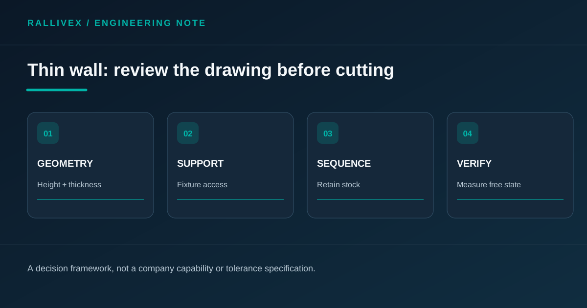
Treat “thin” as a behavior, not a fixed dimension
A wall becomes difficult when cutting forces, tool reach, residual stock and fixturing make it move enough to threaten its requirements. The same nominal thickness can behave differently as height, unsupported span, material or orientation changes. There is therefore no useful universal wall-thickness promise for a drawing. Provide the wall height, thickness, length, corner geometry, material condition and required flatness or profile, with the mating function identified.
Harvey Performance documents how deflection, chatter and tool reach affect thin-wall accuracy. Its discussion of stepped depths and alternating sides is process guidance, not a guarantee that every geometry can be held to the same tolerance. Ask the supplier where the part will be supported at each stage and what stock remains behind the wall during finishing.
Find the point where a drawing change helps
Consider a review if a tall wall is isolated early in the process, a deep adjacent pocket forces long tool extension, or a datum can only be clamped on a fragile finished surface. The design team might add a removable machining tab, change pocket access, increase a local fillet or wall section, or relocate a nonfunctional opening. Each proposal must be checked against mass, fit, sealing, thermal or cosmetic requirements; no drawing should be changed solely for machining convenience.
A wall can be supported by temporary stock, a fixture or a revised cut sequence without redesign. Those options have cost and inspection consequences. Separate a genuinely necessary geometry change from a process choice that the supplier can make while preserving the controlled model.
Plan the order of material removal
Harvey Performance recommends retaining material behind a wall as height is developed and reducing cutter pressure as support stock disappears. Sandvik Coromant similarly emphasizes support and fixturing relative to cutting-force direction for thin-walled components. A practical review asks which side is cut first, whether finishing alternates sides, and whether a final pass occurs with adequate support.
Do not write a specific speed, radial step or cutter into the customer drawing unless it is itself a validated requirement. The correct toolpath depends on material, tool, machine and setup. State the required finished geometry and permitted manufacturing aids, then let the process plan show how it will control distortion.
Specify measurement in the relevant state
A wall can appear satisfactory while held in a fixture yet differ after release. Agree whether the drawing requirement applies in the free state, at an assembly condition or under specified restraint. Identify datums, inspection locations and any temperature or handling conditions that matter. If a flexible wall is intentionally constrained by a mating part, explain that function instead of leaving an inspector to guess.
For an RFQ, include model and drawing revision, wall features and tolerances, functional faces, material specification, quantities and the intended inspection state. Request a manufacturability review before a fixed price or tolerance commitment. This makes the design discussion actionable without inventing a capability number.